Wavefront's and Raypaths
In the previous geophysical methods explored, in particular magnetics and resistivity, we often employed two different descriptions of the physical phenomena being observed. For example, when discussing magnetism we looked at both the strength of the magnetic field and the direction of the magnetic field. When discussing resistivity, we discussed both the electrical potential and current flow.
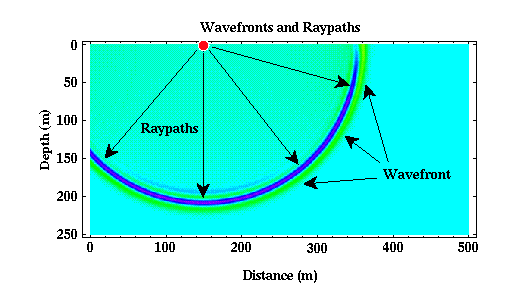
Similarly, there are two equally useful descriptions of seismic waves: wavefronts and raypaths. The relationship between these two descriptions is shown below.

- Raypaths - Raypaths are nothing more than lines that show the direction that the seismic wave is propagating. For any given wave, there are an infinite set of raypaths that could be used. In the example shown above, for instance, a valid raypath could be any radial line drawn from the source. We have shown only a few of the possible raypaths.
- Wavefront - Wavefront's connect positions of the seismic wave that are doing the same thing at the same time. In the example shown above, the wavefront's are spherical in shape. One such wavefront would be the sphere drawn through the middle of the dark blue area. This surface would connect all portions of the wave that have the largest possible negative amplitude at some particular time.
In principle and in practice, raypaths are equivalent to the directions of current flow, and wavefront's are equivalent to the equipotential lines described in the resistivity section. They are also equivalent to field direction and strength in magnetism.
Notice that in this example, wavefront's are perpendicular to raypaths. This is in general always true. So, given either a set of wavefront's or a set of raypaths, we can construct the other. This was also true for current flow and equipotential surfaces in resistivity and for field strength and field direction in magnetism.
Through much of the development to follow, we will use a raypath description of seismic wave propagation. This description will allow for a much easier computation of the propagation times of specific seismic phases, because we will be able to explicitly construct the path along which the seismic wave has travelled before being recorded by our receiver. As we will see next, although the raypaths for the waves shown above are very simple, as we begin to construct models of the Earth that contain speed variations, these raypaths will become more complex.
Seismology
- Simple Earth Model: Low-Velocity Layer Over a Halfspacepg 11
- Head Wavespg 12
- Records of Ground Motionpg 13
- Travel-time Curves for a Simple Earth Modelpg 14
- First Arrivalspg 15
- Determining Earth Structure from Travel Timespg 16
- Derivation of Travel Time Equationspg 17
- High-Velocity Layer Over a Halfspace: Reprisepg 18
- Picking Times of Arrivalspg 25
- Wave Propagation with Multiple Horizontal Layerspg 26
- Travel Time Curves from Multiple Horizontalpg 27
- Hidden Layerspg 28
- Head Waves from a Dipping Layer: Shooting Down Dippg 29
- Head Waves from a Dipping Layer: Shooting Up Dippg 30
- A Field Procedure for Recognizing Dipping Bedspg 31
- Estimating Dips and Depths from Travelpg 32